|
这个在文件中都有(Assembly_instructions.pdf) |
|
附详细制作过程(可惜只有英文的) |
|
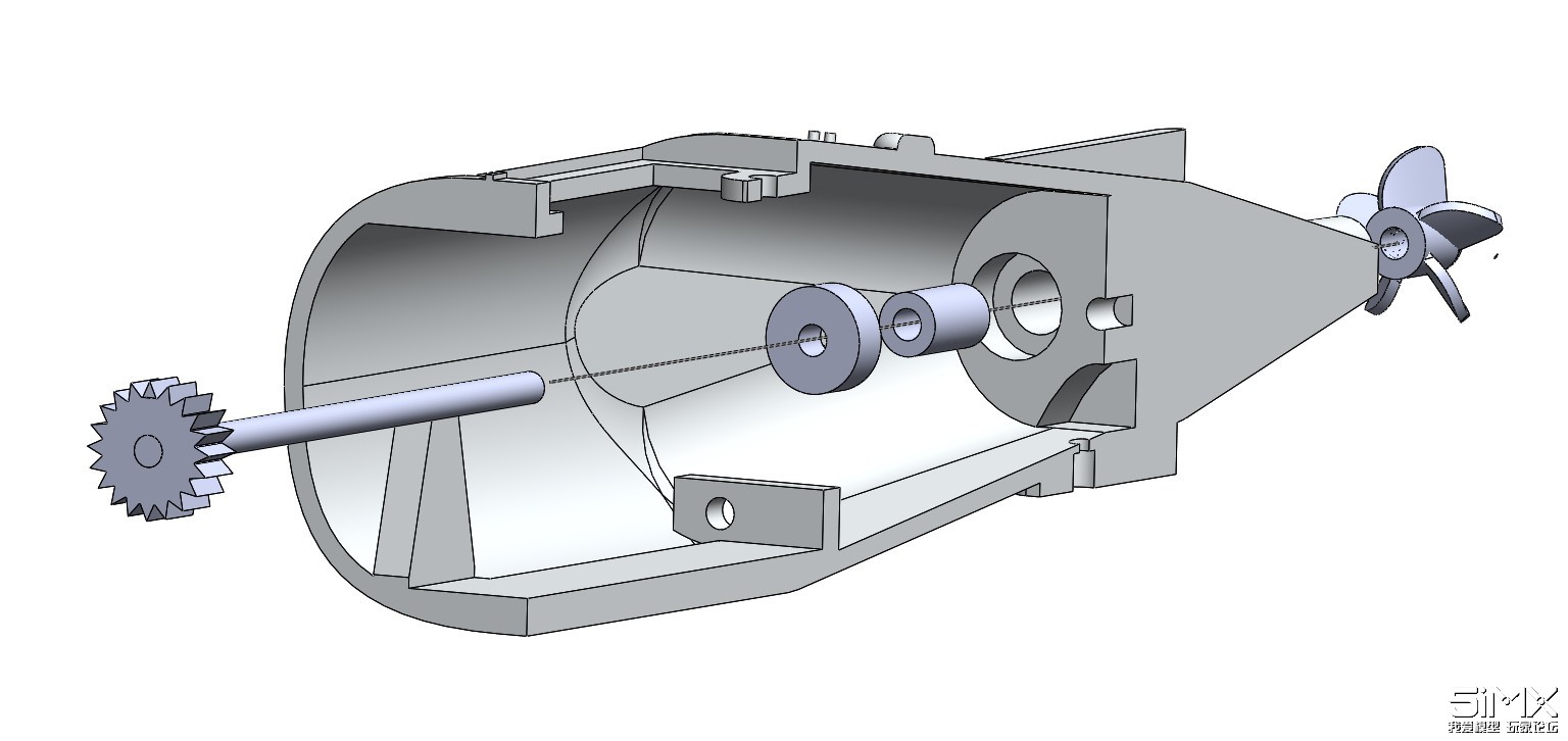
K-141 Kursk (by Ceravyn) v1.5 RC ready Assembly instructions Printed parts required Hull_rear (or hull_rear cut 1 & 2) ........................................................ 1pc Hull_main (or hull_main cut 1 & 2) ........................................................ 1pc Hull_front …........................................................................................ 1pc Hull_bow …........................................................................................ 1pc Prop_5blade …........................................................................................ 2pcs Propshaft_seal …............................................................................ 2pcs Prop_gear …........................................................................................ 2pcs Rear_hatch_seal …............................................................................ 1pc Rear_hatch …........................................................................................ 1pc Rear_side_plane …............................................................................ 2pcs Rear_top_plane …............................................................................ 1pc Rear_small_plane …............................................................................ 4pcs Rudder_seal …........................................................................................ 1pc Rudder_shaft_joint …............................................................................ 1pc Rudder …........................................................................................ 1pc Rudder_pushrod …............................................................................ 1pc Motormount ….........…............................................................................ 1pc Motor_gear …........................................................................................ 1pc Tower (high or low detail) …................................................................. 1pc Missile_silos …........................................................................................ 2pcs Missile_hatch …........................................................................................ 2pcs Front_plane_pushrod …................................................................. 1pc Front_hatch_seal …............................................................................. 1pc Front_hatch …........................................................................................ 1pc Front_plane_joint …............................................................................. 1pc Front_plane …........................................................................................ 2pcs Front_plane_seal …............................................................................. 2pcs Stand_plate …........................................................................................ 2pcs Stand_connecting_rod …................................................................. 1pc Non-printed parts required 2x14mm rod …........................................................................................ 1pc (rudder) 3x70mm rod …........................................................................................ 2pcs (propellers) 2x62mm rod …........................................................................................ 1pc (front planes) 3x55mm rod …........................................................................................ 1pc (motor gear) Bearing 10x3x4 (out-in-depth) …..................................................... 2pcs (propeller shafts) M3 screws …........................................................................................ 4pcs M3 nuts …........................................................................................ 4pcs Thin nails or similar thin studs …..................................................... 4pcs Tools required Glue Drill (to ream the holes into proper diameter) Possibly sandpaper (depends about printing quality) Grease (optional but recommended) 2-sided tape (for mounting battery etc) Electronics used in testing DC-motor 2-6V …............................................................................ 1pc XTD-1109HB Digital Servo …................................................................ 2pcs Servo tester …............................................................................ 1pc 5V power supply …............................................................................ 1pc I went with cheapest possible solution as I don't currently have lots of cash to throw in for this project, but as motor mount is detachable it's easy to modify it to fit any motor out there. Servo mounts are sized to accept 23mm x 13mm x 25mm servos so most of the micro/mini servos should fit easily. Main hull has lots of empty space to fit battery and RC electronics in any configuration necessary. Please keep in mind that water + electricity is not a good combination. I am not in any way responsible for any damages or injuries caused by using this build. This is an experimental proofof- concept build and making it work may require additional work in sealing the hull to be watertight with hot-glue, silicone or similar sealing materials. Propeller shaft assembly 1. Push propeller shaft seals into their holes. (optional but recommended: Apply grease inside the seal and into the propeller shaft tunnel to further improve water-tightness) 2. Push propeller shaft bearings into their holes. 3. Glue propeller shaft gears to the end of the propeller shafts 4. Insert propeller shafts with their gears through the bearing into the shaft tunnel 5. Glue propellers into the end of the propeller shafts Notes: You may need to ream the shaft tunnels into the proper diameter (3mm) depending on the print quality of your printer. Applying grease into the shaft tunnels further decreases chance of water entering inside the hull via the propeller tunnels. This may not be necessary, but due to layers in most of the 3D printed parts it is highly recommended. Silicone grease was tested to work well in this application. Rudder assembly 1. Insert rudder shaft seal into its hole (optional but recommended: Apply grease inside the seal to further improve water-tightness) 2. Glue the rudder shaft into the shaft joint 3. Push the shaft through the rudder seal 4. Glue the rudder to the end of the rudder shaft to complete the assembly 5. Connect rudder pushrod to the shaft joint Notes: Just as with propeller shaft tunnels, silicone grease inserted into the rudder hole and seal further helps to keep water out from the hull. To keep rudder pushrod from detaching from the shaft joint, you may drill a hole through the shaft joint and insert a screw with washer to keep the pushrod in place. However this was not necessary in the test build, and pushrod was kept neatly in place when it was screwed to the servo arm only. Completing the powertrain 1. Insert motor gear into the motor shaft, push the motor shaft into its hole between the propeller shafts. Align motor gear to match the propeller gears and mark the placement with a piece of tape. 2. Remove motor gear with its shaft and glue the motor gear to its place marked in previous step. 3. Fix motor gear shaft into the motor with glue or screw connection. 4. Insert motor with its shaft into the motor mount and secure with screws. 5. Insert motor mount inside the rear hull and secure with two M3 screws. Notes: You may want to add some grease into the gears to reduce noise and smoothen the power transmission. Connection from rudder shaft joint to the servo rod can also be lubricated to smooth out the operation, especially if printing quality isn't the best. Rear hull final assembly 1. Glue the rear planes to their places. These act as stabilizers in this model so make sure they are fixed as horizontally as possible. 2. Glue the small planes to their places. 3. Glue the top plane to its place 4. Insert maintenance hatch seal and attach the maintenance hatch to its place. Depending on the application and water-tightness required from the top of the hull, you might secure it with M3 screw or rely on the fastening clip only. 5. Insert rudder servo to its place between the mounting columns and connect the pushrod with a screw to its arm Notes: The maintenance hatch seal is meant to be splash resistant. It is not meant to provide fully watertight application. If the vessel turns upside-down water will leak through this hatch. If more watersealing is needed, secure the hatch to its place with hot glue or similar sealing. You may need to sand the mating surfaces of the tail planes to form a smooth surface for gluing the planes to. Main hull exterior assembly 1. Glue the missile silo plates into their places in the sides of the main hull 2. Insert small studs (I used pins cut from thin nails) to the missile bay hatch rear mounting holes and connect the rear end of the hatch to the hull. 3. Aligning the front mounting holes, push another set of small pins through the hull wall to connect the hatch and secure it in place. 4. Glue the bridge & command tower to its place. 5. Glue the small side planes to their mating surfaces. Notes: You may need to sand the missile bay hatches a little to make them close properly, especially if you have printed them thin side facing the build platform like I did. Main hull interior assembly (optional) 1. Insert servo for controlling the front planes. You may fix the pushrod now, or in later phase. This is purely visual and the front planes do not effect to the movement of the vessel in any way so if you don't have extra servo's available I recommend skipping this assembly entirely. 2. Insert battery and other necessary electronics to the empty space within the main hull. Notes: Try to keep components at the center to stabilize the weight distribution. Rear planes do stabilize small differences in weight distribution but for example mounting battery to the starboard side and leaving the opposing side empty is not a good idea :) There is no mounting points for battery as I tested this with wired controls and DC power supply, but 2-sided tape is a good solution. Front hull assembly 1. Insert plane shaft seals into their holes, push the plane control rod through one side of the hull. 2. If front plane servo is attached, insert the shaft joint to the plane shaft and push the rod through the hull. 3. If front plane servo is attached, connect the servo pushrod to the shaft joint and glue the shaft joint to its correct placement. 4. Glue the front planes to the both ends of the shaft. Make sure they are both attached in same angle, since the rod tilts both at the same time. 5. Insert the front maintenance hatch seal and attach the maintenance hatch to its place. Secure the hatch, like the rear maintenance hatch, either with the fastening clip only, or with additional screw. Notes: Like with the rear hatch, the front hatch seal is splash resistant only. It isn't meant to provide 100% waterproofing. If this is necessary, further fix the maintenance hatch with glue. If you don't want front planes to move, you can seal the shaft holes shut and simply attach the front planes to their mounting points with glue. Finishing steps Securely glue all the parts of the hull together. Make sure the seams are glued properly to avoid leaks, and all the wiring and other parts you may need access to are brought close to the maintenance hatches so you don't need to take it completely apart if some servo wire comes loose. There is also a display stand provided, this is a simple three-piece assembly. Glue the rod between the two side plates and you're done. That's it. You have now built your very own K-141 Kursk nuclear submarine. |
 /2
/2 
 收藏
收藏