As promised on my “Solent Turbojet” page here comes the design of my simple balancing setup. 如所承诺的那样在我的“索伦特涡喷”网页的设计来这里我简单的平衡格局。 Most of the parts are made out of 10mm aluminium plate, milled to shape. 大多数地区都在10毫米铝板,碾磨形成。 My little CNC mill had to suffer bad mistreatment once again, at least the milling tool (all work was done with a single 3mm carbide tool). 我的小数控磨坏了遭受虐待再次,至少铣刀(所有工作是在一个单一的采用3mm硬质合金刀具) 。
----------------------------------------------------- Inserted 01/30/2001 ------------------------------------------------- -------------------------------------------------- ---插入 2001年1月30号----------------------------------------- --------
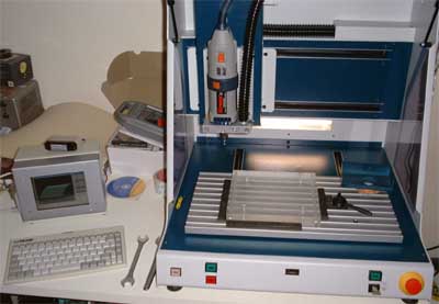 Upon special request here a picture of my CNC mill is added. 经特别要求 , 在这里的照片是我的数控磨说。 It is an isel CPM 3020 < http://www.isel.de > , initially bought for making front panels and PCBs for prototype electronic equipment. 这是一个伊瑟尔每千次展示费用3020 “ http://www.isel.de ” ,最初购买决策前面板和多氯联苯为原型的电子设备。 It proved to be useful for many other things, though. 它被证明是有益的许多其他事情,但。 Currently it is capable of three dimensions, while the controller inside will power a fourth actuator. 目前它有能力三个方面,而控制器内将权力四分之一器。 So I will probably add a rotational axle soon. 所以 , 我可能会增加一个旋转轴很快。 The motion range of the three axles is 300x200x120mm³. 该项议案范围三个车轴是300x200x120mm ³ 。 One of the goodies is that the cabinet can be closed and a vacuum cleaner connected as to extract the dust. 一个东西是 , 内阁可以关闭和吸尘器连接作为提取灰尘。 The small PC on the left is an industrial slot-CPU 486 (super-sophisticated high performance, latest model 10GHz... ;-) equipped with a 6” TFT display. 小电脑的左边是一个工业插槽处理器486 (超精密的高性能,最新型10GHz ... ;-)配备6 “ TFT液晶显示屏。 The speed of this PC is of no concern at all as it will be faster than the mechanical components of the mill in any case. 速度 , 电脑是没有关注 , 因为它在所有将快于机械部件的工厂在任何情况下。 It is equipped with a networking adapter to upload the vector data from the CAM system on my workstation. 它配备了一个网络适配器上载矢量数据从CAM系统在我的工作站。 ----------------------------------------------------------------------------------------------------------------------------------- -------------------------------------------------- -------------------------------------------------- -------------------------------
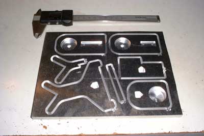 This is what the plate looked like after about three hours of milling (oh yeah, my landlady LOVES it ;-). 这是什么模样板后约三小时的铣削(噢,我的房东喜欢;-) 。 All contour cuts and “pockets” are 10mm in depth except the receptacles for the piezo transducers, which are stepped as to provide a proper seat for the transducers. 所有轮廓削减和“口袋”是一零毫米深入除了贮的压电传感器,这是加强以提供适当的座位传感器。 When I mill multiple parts out of a single plate I usually set the cutting depth so as to leave approx. 当我厂多个部分的一个单一的板我通常设置切割深度 , 以假约。 50µm of material at the bottom intact to prevent the finished parts from falling out. 示50μm的材料底部完整 , 防止成品零件掉下来。 They can easily be cut out with a sharp knife afterwards. 他们可以很容易地切断了与尖刀之后。
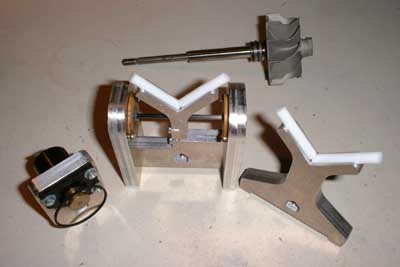
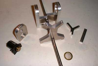 And here are the parts ready for further machining. 这里是部分准备进行进一步的加工。 They are cut out and cleaned and then set together so you get an idea how the device will look when finished. 他们切断了和清理 , 然后设置在一起 , 以便你的想法如何装置将完成时。 All the different plates will be clamped to a steel shaft to ensure rigidity. 所有不同的车牌将被钳制到钢铁骨干 , 以确保刚性。 The front “Y” part is the fixed bearig, the “Y” sitting on the right will be connected with a spring type brass sheet to the center of the second part sitting on the shaft. 前面的“ Y ”部分是固定bearig ,在“ Y ”型坐在权利将与春季型黄铜板材的中心第二部分坐在轴。 This brass sheet will allow slight radial movement of this bearing while still providing rigidity in axial direction. 这将允许黄铜板材略有径向运动的同时仍能提供刚性轴向方向。 This small movement will be transferred by a connecting rod (not yet displayed) to two piezo transducers, forming a push-pull arrangement. 这个小小的运动将移交由连杆(尚未显示)两个压电传感器,形成了推挽安排。 One of the transducers can be seen in the foreground. 一个传感器可以看出在前台。 The balancing shaft will be driven by a small electric motor (on the left) via a belt. 平衡轴将推动一个小型电动马达(左侧)通过皮带。 This particular motor was salvaged from an old VCR. 这种特殊的汽车打捞从旧录像机。 I checked about 20 motors from my “collection” until I found this one which was running sufficiently smooth. 我检查了20汽车从我的“集合” , 直到我发现这是一个充分的顺利运行。 The “bearings” will be formed by cylindrical PTFE pieces of 6mm diameter that will have to be inserted into the inner side of the “arms” of the “Y” shaped bearing parts. 的“轴承”将成立圆柱聚四氟乙烯件6毫米直径将必须插入到内侧的“武器”的“ Y ”型形轴承零件。 This way it is possible to avoid ball bearings that will always induce a small amount of imbalance, and allow balancing of rotors with different shaft diameters without having to modify the setup. 这种方式能够避免球轴承 , 将始终诱导少量的不平衡,并允许平衡转子轴直径不同而无需修改安装。 Once the mechanical components are finished I will design the electronics. 一旦机械部件 , 我将完成设计的电子产品。 If somebody is interested in details I might convert the drawings from my CAD/CAM system to DXF and publish them to this site (the information in these is rather limited though, because most of the design I did in crude free-hand sketches). 如果有人有兴趣的细节我可能转换图纸从我的CAD / CAM 系统 , 以DXF文件并将其发布到这个网站(中的信息 , 这些是相当有限的,因为大多数的设计我在原油徒手草图) 。
Added 12/19/2000 时间 00年12月19号
 Today I completed the mechanical work on the balancer. 今天 , 我完成了机械工作的平衡。 Unfortunately I wrecked both piezoelectric transducers while matching the length of the connecting rod. 不幸的是 , 我既破坏压电传感器 , 同时匹配的长度连杆。 They are inexpensive, but I'll have to order them and thus progress will be delayed a little. 他们是廉价的,但我要命令他们 , 从而取得进展将推迟一点。 The PTFE bearing sticks aren't yet fixed to the bearing supports, they are just sitting in the slots milled into the inner sides of the “Y” legs. 聚四氟乙烯轴承支尚未固定在轴承支持,他们只是坐在插槽内碾磨成两边的“ Y ”型腿。 Kerosene works great for lubricating them! 煤油伟大工程的润滑他们! Some experiments revealed that the electric motor might be a little weak for this purpose, but I still can try a smaller belt pulley. 一些实验表明电动机可能有点弱为此目的,但我仍然可以尝试较小皮带轮。
Added 12/29/2000 时间 2000年12月29号
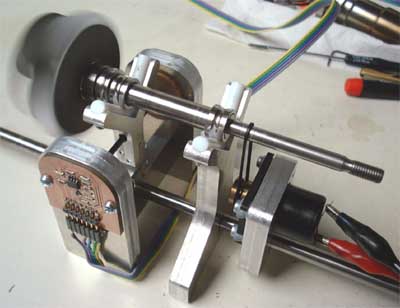 Finally I got the spare piezoelectric transducers and finished some simple high-impedance signal amplifiers. 最后我得到了备件压电传感器和完成一些简单的高阻抗信号放大器。 On the Scope the imbalance signal can clearly be observed, the setup is increadibly sensitive. 的范围不平衡信号可以清楚地看到,安装是increadibly敏感。 Yet I have to build some kind of trigger circuit to flash a LED in order to find the “heavy” side of the item to be balanced. 然而 , 我必须建立某种形式的触发电路的Flash一个LED , 以便找到“重型”一侧的项目来加以平衡。 This will also contain all the power supplies (for motor and amplifiers). 这也将包含所有的电源供应器(电机和放大器) 。 On this particular turbocharger turbine wheel I used the inner races of two ball bearings to prevent the shaft from moving axially. 关于这一特定的涡轮增压器涡轮我用站内的两个球轴承 , 以防止轴轴向移动。 Despite of this the quality of the surface of these races is very good, thus generating low noise that would effect a nasty “hiss” superimposed to the signal. 尽管本的质量 , 这些表面的比赛非常好,从而产生低噪音 , 将影响肮脏的“嘘”的叠加信号。
Added 01/12/2001 时间 2001年1月12日
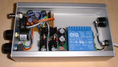
Well, at least the electronic components for the trigger circuit made it. 那么,至少在电子元件的触发电路了。 So no cabinet for the electronics yet - bad luck. 因此 , 没有内阁电子尚未-运气不好。 And this is what the balancer currently looks like: 这就是平衡目前看起来是这样的:
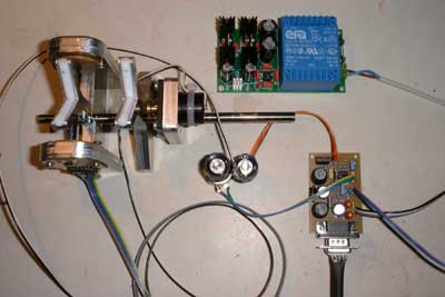 On top with the blue transformer sits the power supply. 顶部的蓝色坐在变压器供电。 I had some PCBs left from a design I did earlier for a scientific research project, so I used one of the power boards to build a symmetric power supply (+8 and - 8Volts). 我有一些遗留的多氯联苯的设计我早先的科学研究项目,所以我用一个电源板 , 以建立一个对称的电源供应器( 8 和- 8Volts ) 。 The small PCB in the lower right contains the Trigger/LED flasher circuit as well as a simple PWM motor controller. 小电路板右下角包含触发/发光二极管闪光电路 , 以及一个简单的PWM马达控制器。 The two variable resistors in the center are for controlling motor speed and trigger level. 两个可变电阻的中心控制电机转速和触发电平。 The rest are mostly wires ;-). 其余大多是电线;-) 。 I use an ultrabright white LED, and this is really unbelievably bright. 我使用ultrabright白光LED ,这确实是令人难以置信的明亮。 The circuit worked more or less immediately, I just had to change the timing capacitor for the PWM to a smaller value. 该电路的工作或多或少立即,我不得不改变时间电容器的脉宽调制到一个较小的值。 The trigger circuit sensitivity well matches my expectations, it recognizes easily if one shouts at the balancer ;-). 触发电路的灵敏度以及符合我的期望,它也承认 , 如果一喊很容易在平衡器;-) 。 It also turned out to be a good choice to spend some money for a ten-turn variable resistor for adjusting the trigger. 它也被证明是一个不错的选择 , 花些钱为10 -反过来可变电阻的调整触发。 I will soon do some rectifications to the schematics and then publish them to this page. 不久我将做一些改善工程的原理图 , 然后把它们发布在此页上。
Added 01/14/2001 时间 2001年1月14号
Finally I extracted both the schematics of the high-impedance buffers and the trigger circuit from my electronics CAD system and converted them into jpegs. 最后 , 我的图表中提取的高阻抗缓冲器和触发电路从我的电子CAD系统和转换成JPEG文件。 These are probably a little small (as server space is a concern), but readable. 这些都是可能有点小(如服务器空间是一个关注的) ,但可读性。 Both circuits are tested to work properly. 这两种测试电路正常工作。 Just click on the captions below to display (or download) them. 只需点击标题下面的显示器(或下载)他们。
缓冲区示意图( 30,000 )
触发示意图( 66k )
 Since my balancing setup incorporates two piezo transducers in push-pull configuration, I built two of the buffers, and so the signals from both transducers will have to be subtracted from each other. 自从我平衡安装集成了两个压电传感器在推拉配置,我内置两个缓冲器,因此,信号从传感器将不得不减去对方。 But as I discovered, the piezo disk in the transducers is not necessarily polarized in the same direction on each, an addition of the signal must also be possible. 不过 , 正如我发现,压电盘传感器不一定极化在同一方向上,每个增加的信号也必须是可行的。 This is done by connecting the corresponding output of the first buffer to the inverting input of the second. 这是通过连接相应的输出第一缓冲区的反相输入第二。 Either the "negative or differential" (for opposite polarity transducers) or the "positive" (for same polarity transducers) output of the first buffer is routed to the "negative input" of the second buffer. 无论是“消极或差别” (为相反极性转换器)或“积极的” (对相同的极性转换器)输出的第一个缓冲区发送到“负输入”第二缓冲区。 Imbalance signal is measured at the "negative or differential output" of the second buffer. 不平衡信号的测量“消极或差分输出”第二缓冲区。 All other inputs/outputs are left open, the ground and power supply pins are connected in parallel. 所有其他投入/产出打开,地面和电源引脚并联。 For simplicity I added a schematic of this (01/31/2001), klick below. 为了简洁明了我还示意图本( 2001年1月31日) , klick如下。 互联diagramm ( 49k )
The nomenclature of the inputs/outputs is strictly speaking not exactly correct, but it serves its purpose ;-) 名目的输入/输出是严格地说不完全正确的,但它的目的 , ;-)
The transducers are just piezo buzzers (27mm brass sheet disk with piezo-ceramic material bonded to one face), and in Europe they are available through Conrad Electronic < http://www.conrad.com > (order No. 712-930). 该传感器只是压电蜂鸣器(二七毫米黄铜板材磁盘与压电陶瓷材料保税一个面) ,并在欧洲 , 他们都可以通过电子康拉德“ http://www.conrad.com ” (订单号712-930 ) 。
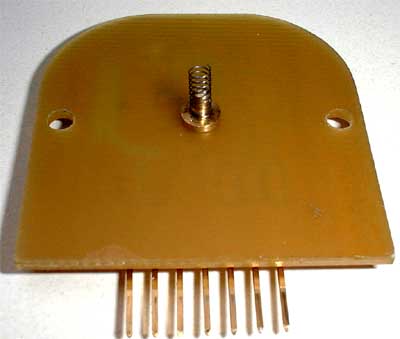 I connected the piezo disks by a small spring, as displayed in this picture. 本人连接压电磁盘由一个小型的春天,作为显示在此图片。 The ground return of the piezo discs is accomplished through the structural parts of the balancer. 返回地面的压电光盘是通过结构部分的平衡。
The trigger PCB consists of two parts, first (upper half of the schematic) the trigger and constant-current LED drive and second (lower half) the PWM motor current controller. 触发电路板由两部分组成,第一(上半部分示意图)的触发和恒定电流LED驱动器和第二届(下半部分)的PWM电动机电流控制器。 Both circuits are straight-ahead designs, and if the motor controller isn't required, it simply can be left away. 这两种电路直前的设计,如果电机控制器是不是必需的,它只是可以离开了。 The BNC jack can be connected to a scope or a true-RMS AC voltmeter to measure the degree of imbalance. 是的BNC插孔可以连接到范围或一个真正的有效值交流电压表测量程度的不平衡。 It is very important when doing measurements with this setup that it is seated firmly to avoid resonances. 这是非常重要的测量时做此安装 , 这是坐在坚决避免共振。 If they nevertheless occur, a rotational speed should be selected that is way off the resonance frequencies. 如果他们仍然发生,转速应选择是遥远的共振频率。
The Motor current controller can be loaded with up to 1A, depending on the inductors. 电机电流控制器可以装载高达1A ,取决于电感。 Usually the motors for turning the part to be balanced won't need to be very powerful, so this current should be more than enough. 通常是电动机的转动部分必须兼顾不会需要非常强大的,所以当前应绰绰有余。 The Motor RPM isn't stabilized, so it needs to be adjusted properly by hand. 电机转速并不稳定,所以需要调整适当的手。
Added 01/14/2001 时间 2001年1月14号
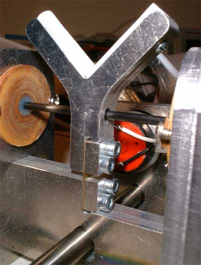 Upon special request I added this close-up of the transducer assembly. 经特别要求 , 我已将这近摄的传感器大会。 The moving “Y” has a 5 mm hole drilled through it, through which runs the carbon fibre reinforced epoxy connecting rod. 移动的“ Y ”有5毫米钻孔通过它,通过它运行碳纤维增强环氧树脂连杆。 It is cross-drilled and fixed with a 0.8mm steel needle. 这是交叉钻孔和固定的0.8钢针。 The ugly-looking piezo disk retainers are made from plastic (in this case reinforced phenolic resin, I just had no other material handy, looks and smells like s**t ;-). 丑陋的前瞻性压电磁盘家臣是由塑料(在这种情况下 , 加强酚醛树脂,我只是没有其他材料方便,外观和味道像县**吨;-) 。 The spring brass sheet accepts the axial and gravitational forces, but allows radial movement in one dimesion. 春季黄铜板材接受轴向和引力部队,但允许径向运动的一个dimesion 。 The steel rod that connects the different shaft supports and the motor mounting plate is clamped with a small screw (M3). 钢抽油杆连接不同轴支持和电机安装板是钳制小螺丝(立方米) 。
Finished 01/29/2001 完成 2001年1月29日
Today I got the missing cabinet for the electronics. 今天 , 我得到了失踪内阁的电子产品。 After CNC milling the openings for the variable resistors and the jacks I assembled the components. 在数控铣床的开口的可变电阻和插孔我组装的部件。
 There's still some space left in the cabinet, but I cannot imagine what's missing ;-). 还有一些空间 , 留在内阁,但我不能想象有什么遗漏;-) 。
The mains switch is located on the rear cover along with the AC inlet, all the other knobs and jacks are on the front. 电源开关位于后盖一起交流入口,所有其他的旋钮和插孔都在前线。
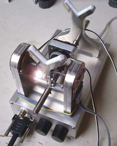 This is a view of the finished balancer. Well, perhaps I'll add some covers for the buffer PCBs later, but for now I'm absolutely satisfied with the result. 这是鉴于成品平衡器。好吧,也许我会添加一些包括多氯联苯的缓冲区后,但现在我非常满意的结果。 The white spot is the LED so you get an idea how bright it is. 白斑是发光二极管 , 使你的想法是多么美好。 I already did some balancing with the trigger / LED assembly and the result is almost perfect. 我已经做了一些平衡与触发/发光二极管大会和结果几乎是完美的。 I used textile adhesive tape as counterweight, and the balancer will detect a piece of about 2mm² area. 我用纺织胶带作为配重,以及平衡将检测的一块面积约2毫米² 。 I guess the balancing result, once I have acquired some experience with this device, can be better than 1mg*cm. 我猜的平衡结果,一旦我获得了一些经验 , 有了这种设备,可以优于1毫克*厘米。 This accuracy isn't limited by the sensitivity of the pickup system, but by the quality of the shaft surface and the noise generated by the rotation. 这不仅限于准确性的灵敏度拾音器系统,但在质量 , 轴表面和噪声所产生的轮换。 Maybe even the vanes of the wheels will produce enough eddies in the air to affect the result when balancing in the low milligramm regions. 甚至在叶片的轮毂生产足够的漩涡将空气中的影响时 , 平衡的结果在低milligramm地区。
Another good news is that an oscilloscope is definitely not necessary as the ten-turn trigger preset will be just fine for estimating the quantity of imbalance and evaluating the condition of least imbalance. 另一个好消息是 , 示波器肯定不是必要的 , 因为十年反过来将触发预设只是罚款的数量估计和评价不平衡的状况至少不平衡。 In some details the device might still be simplified. 在一些细节的设备仍然可以予以简化。
Added 03/19/2001 时间 2001年3月19号
A new page containing information about available electronics parts and assembly instructions has been added. 一种新的一页的资料 , 提供电子零件和组装说明已添加。
| 


 /1
/1 


 发表于 2008-8-7 21:29

 收藏
收藏